

The test wave moves from the laser to the target, while the reference wave travels upward and then right toward Beam splitter 3.
Toolkit · static and interactive
Laser Doppler vibrometry
Corrected optical layout
How the beams travel through a heterodyne LDV.
The approved static schematic establishes the optical order. The page now includes theme-aware dark and light versions of the static drawing, while the interactive wave view below shows how target motion changes the returned wavelength and how the returned and reference waves produce a detector beat.
Static schematic + interactive wave animationCorrect beam order and component order
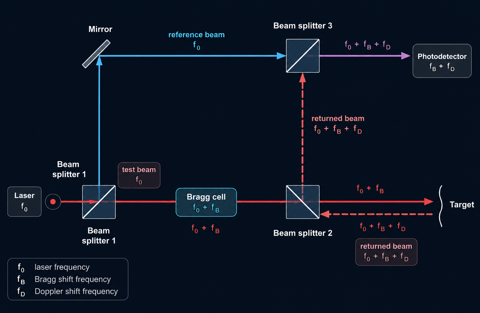
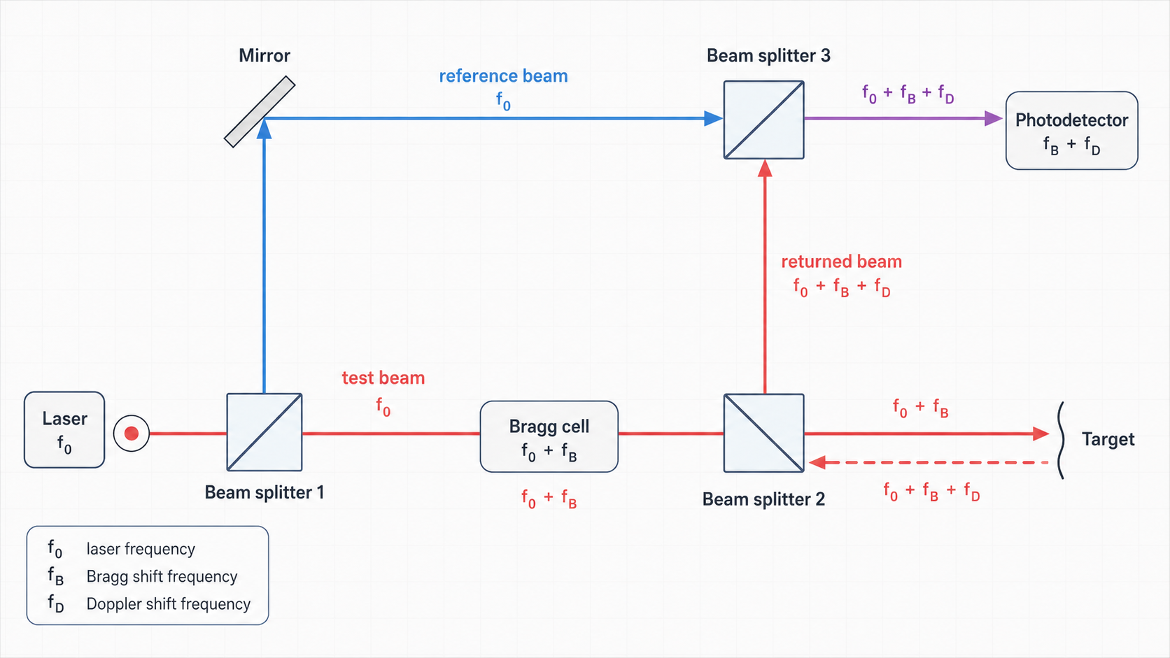
The static schematic below is the current approved preview integrated directly into the website. It shows the simplified optical route with corrected beam-splitter orientation: beam splitter 1 sends part of the beam upward into the reference path, beam splitter 2 directs the returned beam upward to beam splitter 3, and beam splitter 3 combines the returned beam with the reference beam before the photodetector.
Website prototype v141 · compact static + interactive + light mode
Frequency labels in the layoutExpand or collapse the colour and frequency key.
Outgoing test beam
Leaves Beam splitter 1 as f₀ and becomes f₀ + f_B after the Bragg cell.
Returned beam
Returns from the moving target as f₀ + f_B ± f_D.
Reference beam
Leaves Beam splitter 1 as unchanged f₀ and travels through the mirror to Beam splitter 3.
Detector beat
At the photodetector the mixed signal is f_B ± f_D.
Target motion
The target motion is the physical source of the Doppler term f_D.
Interactive wave view
Follow the travelling waves from the laser to the target and back. The outgoing and reference fields always propagate away from the laser. The returned field always propagates from the moving target through Beam splitter 2 to Beam splitter 3; target motion changes its crest spacing, not its travel direction. The combined light then travels to the photodetector.
Live wave view
Biological presets:
Displacement toward sensor0.0 nm
Line-of-sight velocity0.000 mm/s
Doppler shift0.00 kHz
Detector beat40 MHz + 0.00 kHz
As the target moves toward the sensor, successive returned crests are compressed; as it moves away, they are expanded. A retarded-time wave history keeps every crest travelling from the target back toward Beam splitter 3.
After Beam splitter 3, the cyan reference component and pink returned component travel right together. Their purple sum grows and shrinks through constructive and destructive interference.
Teaching view: optical wavelengths, Bragg shift, Doppler wavelength change and beat rate are deliberately exaggerated and are not drawn to scale. The animation-speed control changes only playback speed, not the calculated physical values.
In the approved simplified layout, the lower test beam passes through the Bragg cell before illuminating the target.
The returned beam contains the fixed Bragg offset and the velocity-dependent Doppler contribution: f₀ + f_B ± f_D.
Beam splitter 3 overlaps the unchanged reference beam and the returned beam. Their frequency difference produces the detectable beat f_B ± f_D.
Model conventions in this static phase
- This is a simplified single-point heterodyne LDV layout, drawn for clarity rather than exact mechanical packaging.
- The colours separate optical roles, not absolute physical wavelengths or detector sensitivities.
- The target-motion arrow indicates the origin of
f_D; for clarity this static phase illustrates the case of motion giving a positive Doppler contribution+f_D. - The exact sign in
f₀ ± f_Ddepends on the direction of target velocity relative to the optical axis.
Correctness and grounding
The static and interactive views follow the approved schematic developed from the supplied references and the LDV sources previously checked for this project.
- Your supplied schematic references and iterative corrections defining the beam-splitter orientation, outgoing test path, reference path, returned path, recombination and photodetection.
- Previously checked LDV explanatory material from Polytec and a metrology reference from NIST / Acta IMEKO, already incorporated earlier in this project.
- The user-provided YouTube link was treated as additional context for simplicity of explanation, but this environment could not directly inspect the video content.